Arduino Projects
What's here?
The focus on this part is to know the basic operations of a
Arduino Microcontroller. We used Arduino Uno to simulate
some basic coding techniques to enhance our knowledge.
Objective
The goal is to make simple arduino circuits using arduino to understand the basic coding. The materials we used are blinking lights, arduino uno, ultrasonic sensor, resistors etc.
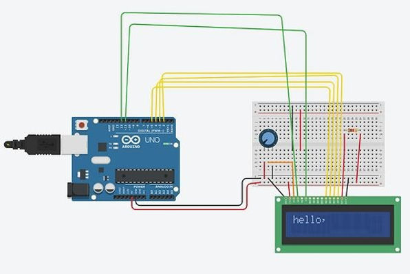
Arduino Circuits
Ultrasonic Sensor
Ultrasonic sensors uses sound wave to measure the distance of an object. For different distances it can show the distance in serial monitor in both centimeters and inches.
void setup() {
pinMode(trigPin, OUTPUT);
pinMode(echoPin, INPUT);
Serial.begin(9600);
Serial.println("with Arduino UNO R3");}
void loop() {
digitalWrite(trigPin, LOW); delayMicroseconds(2);
digitalWrite(trigPin, HIGH); delayMicroseconds(10);
digitalWrite(trigPin, LOW);
distance = duration * 0.034 / 2; Serial.print("Distance: ");
Serial.print(distance); Serial.println(" cm"); }
Two LED Lights
Blink two LED lights using simple coding. Connect the blue light to pin 13 and red light to pin 5. Use 220 ohm resistor for both light to avoid fusing the lights.

int ledPin = 13;
int ledPin2 = 5;
void setup()
{
pinMode(ledPin,OUTPUT);
pinMode(ledPin2,OUTPUT);
}
void loop()
{
digitalWrite(ledPin,HIGH);
digitalWrite(ledPin2,LOW);
delay(1000);
digitalWrite(ledPin,LOW);
digitalWrite(ledPin2,HIGH);
delay(1000);
}
Temperature Sensor
The temperature sensor working with Arduino, it gets environment data from the input device and show it in the serial monitor. The real time data shows voltage, degree in C and F.


void setup()
{
pinMode(LED_BUILTIN, OUTPUT);
}
void loop()
{ ILTIN, HIGH);
delay(1000); // Wait for 1000 millisecond(s)
digitalWrite(LED_BUILTIN, LOW);
delay(1000); // Wait for 1000 millisecond(s)
}

7 Segment Display
The 7 segment display uses binary code to display the number 1 to 10 and a dot. Each pin has two input options, 0 or 1. Input 0 means part of that segment's light is off and input 1 means the light is on. The code below displays the number 9.
int pin_a = 7;
int pin_b = 6;
int pin_c = 5;
int pin_d = 10;
int pin_e = 11;
int pin_f = 8;
int pin_g = 9;
int pin_p = 4;
int numTable[10][8] =
{//a b c d e f g dp
{1, 1, 1, 1, 1, 1, 0, 0}, //0
{0, 1, 1, 0, 0, 0, 0, 0}, //1
{1, 1, 0, 1, 1, 0, 1, 0}, //2
{1, 1, 1, 1, 0, 0, 1, 0}, //3
{0, 1, 1, 0, 0, 1, 1, 0}, //4
{1, 0, 1, 1, 0, 1, 1, 0}, //5
{1, 0, 1, 1, 1, 1, 1, 0}, //6
{1, 1, 1, 0, 0, 0, 0, 0}, //7
{1, 1, 1, 1, 1, 1, 1, 0}, //8
{1, 1, 1, 1, 0, 1, 1, 0}, //9};
void setup()
{
for (int i = 4; i <= 11; i++)
{
pinMode(i, OUTPUT);
}
}
void loop(){for (int i = 0; i < 10; i++)
{
digitalWrite(pin_a, numTable[i][0]);
digitalWrite(pin_b, numTable[i][1]);
digitalWrite(pin_c, numTable[i][2]);
digitalWrite(pin_d, numTable[i][3]);
digitalWrite(pin_e, numTable[i][4]);
digitalWrite(pin_f, numTable[i][5]);
digitalWrite(pin_g, numTable[i][6]);
digitalWrite(pin_p, numTable[i][7]);
delay(200);
}
}