Acerca de
Self Driving Robot
Our final goal is to build a self sustaining autonomous rover. Our vision is to turn it into a environment monitoring system based on ARM and IoT. This GPS Guided Robot can be controlled using an android app. It will be able to reach a certain way point using GPS. The robot constantly checks to see if it is within 0 meters of the GPS position, if it is then the App display will read "Destination Reached".
Materials Required

Robot Chasis

L293D Motor Control Board

Jumper Wires

Arduino Mega

HC-06 Bluetooth
Module

QMC 5883L Magnetometer
Ultrasonic
Sensor

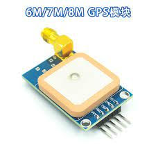
Ublox Neo 6m
GPS Module
Software Requirement
1. Arduino Ide for Windows or IOS
2. Several Libraries in Arduino
3. MIT app inventor for android app
4. Linux environment for sensor data processing
5. ThingSpeak Cloud
How to make the robot
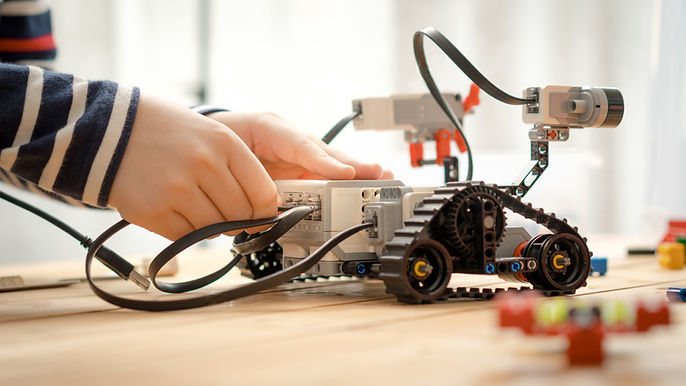
We decided to divide the project up into smaller sections. First we built a robotic platform on which we set up and organized our other components . We made the robot a very rugged prototype because it will mostly be used outside.
Our steps was simple, first build a small robot using Arduino, a motor shield, a battery pack. Next we implemented the control system of the robot. After looking at just about every option possible we decided to utilize a cell phone using Bluetooth. So, first we built the simple robot, attach the motor controller and Arduino; then we made the robot make simple movements without Bluetooth. Next, we added Bluetooth to the robot by installing a Bluetooth module and designed an App using MIT App Inventor to control the robot; moving forward, backward, left and right.
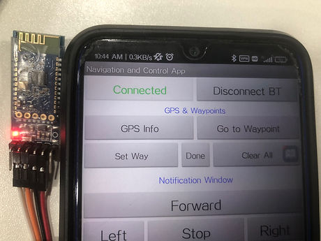
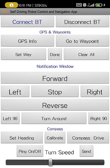
After the coding is done and
the code is uploaded to arduino,
we can connect the bluetooth
module to our smartphone.
Once connected, the app will
change connect bluetooth status
to connected and the red light
of bluetooth module will stop blinking at once.
Additionally we added a magnetometer (compass) in the robot to give it a sense of direction. It is important to achieve better GPS navigation.
After the code is uploaded, the gps module will automatically connect to satellites to give gps coordinates. Typically Neo6m connects to one staellite in indoors and upto 4 satellites outdoors.
At the end, we added a Ultrasonic Sensor to avoid collision to the system. We decided to use a Power Bank that feeds power to the L293d motor controller which in turn provides power to the Arduino and all other parts.
Adding a magnetometer (compass) to the robot is not optional. If the robot does not know which direction it's pointed, then it will be very difficult for it to know which way to start it's journey. "But doesn't a GPS know which direction it's headed in?" Yes, but only after it has traveled a certain direction for an extended period of time. We don't have that kind of battery power to waste, we need a constant update on our direction so that we can create the quickest route to our destination. We cannot stress enough how important it is to get this part of the project Exactly Right. Once we get our magnetometer connector pins soldered we will need to mount it to the robot. It needs to be far enough away from the motors and anything else that could cause electromagnetic interference. We can use just about anything for a mast, just make sure it is not made of metal and also be sure not to use metal screws to attach it to the mast.
For this whole thing to work, we need to add some libraries into the arduino library. If these Libraries are not installed, you will have compile errors when trying to Compile/ or Verify the code.
The Wire Library, The I2Cdev Library, The Servo Library, The Software Serial Library, QMC5883L Magnetometer Library, The AFMotor Library, The TinyGPS++ Library
After we are done with all the wiring, we can compile and upload the code to the arduino. The wiring pins connection is shown below.


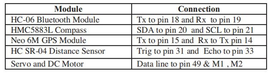
Now before we can mobilize our robot, we need to compile and upload the codes to the arduino mega. The code for this project can be found here.

Control and Navigation
For control and navigation, we will use a mobile app to connect to the robot via bluetooth. We used MIT app inventor to build our app. For now, our app is only available for android platform.
Innovation
Two of the most talked about self-driving advancements come from Google and Tesla. They take different approaches: Google is using lidar (a radar-like technology that uses light instead of radio waves) sensor technology and going straight to cars without steering wheels or foot pedals. Tesla has rolled out a software system called Autopilot, which employs high-tech camera sensors as a car’s “eyes,” to some of its cars already on the market.
While technologies and capabilities continue to evolve toward making autonomous vehicles a reality, there are some hurdles. Right now, autonomous cars are legal only in a few U.S. states, as regulators weigh how to best ensure their safe interaction with standard human-driven vehicles.
In our project, we tried to take a simple way of navigating. For this project, our navigation technique first detects obstacle in left, right and front, and then compares the furthermost obstacle and go that way to obtain maximum closeness to destination.
Similar Tech Available in Market
Top self driving car companies in market now

There has been incremental, but steady, progress in the development of self-driving cars. Some form of driver-assistance technology focused on safety is now inside most new vehicles. You can learn everything about Self driving cars here. The dream of the self-driving car — you get in, program your destination, ease the seat back, and let the car take you where you need to go. Read a book. Maybe take a nap or play a game on the in-car entertainment screen. Regardless, you will not need to watch the road. The car will get you there and back safely. It's not a dream anymore. Know more about the present status of self driving cars here.
The global self-driving cars market size is projected to grow from 20.3 million units in 2021 to 62.4 million units by 2030, at a CAGR of 13.3%. Safety features are an important prerequisite for automotive customers across the world.

Key Tech Analysis
01. Arduino Mega

They main component of this project is the Arduino Mega. It acts as the central processing unit of the robot. The Mega 2560 is a microcontroller board based on the ATmega2560. It has 54 digital input/output pins (of which 15 can be used as PWM outputs), 16 analog inputs, 4 UARTs (hardware serial ports), a 16 MHz crystal oscillator, a USB connection, a power jack, an ICSP header, and a reset button. It contains everything needed to support the microcontroller; simply connect it to a computer with a USB cable or power it with a AC-to-DC adapter or battery to get started. The Mega 2560 board is compatible with most shields designed for the Uno and the former boards Duemilanove or Diecimila.
For the same work, we could use a arduino uno. But an arduino uno has lesser number of interface pins. Therefore it may not be able to support the range of components we need to use for this project. That is why, we think using a megaboard is the right option here.
Advantages of The Mega:
-
Low power consumption with fast start-up
-
Easier to use, with 8-bit microcontroller being less complex than 32/64 bit versions
-
QTouch Suite allows for ease of exploring, developing and debugging own touch applications
-
Patented Adjacent Key Suppression technology allows for unambiguous detection of key events
Disadvantages of The Mega:
-
Limited amount of flash memory write cycles restricts the capacity to be flashed when programmed to pc
-
Naturally lacks incremental performance compared to higher bit microcontrollers.
02. L293D Motor Shield

One of the easiest and inexpensive way to control dc and servo motors through arduino is to interface with L293D Motor Driver Shield. It’s a full-featured motor shield – perfect for many robot and CNC projects.
The L293D is a dual-channel H-Bridge motor driver capable of driving a pair of DC motors or single stepper motor. As the shield comes with two L293D motor driver chipsets, that means it can individually drive up to four DC motors making it ideal for building four-wheel robot platforms. The shield offers total 4 H-Bridges and each H-bridge can deliver up to 0.6A to the motor. The shield also comes with a 74HC595 shift register that extends 4 digital pins of the Arduino to the 8 direction control pins of two L293D chips.
There are many other version of motor shield or motor control driver available on the market. But we are using this one because this is the cheapest, easiest to use and has less complicated function.
03. Navigation Panel


To achieve perfect autonomous navigation, we need to carefully calibrate and use all 3 of these module with the arduino.
HC-06 is a Bluetooth module designed for establishing short range wireless data communication between two microcontrollers or systems. The module works on Bluetooth 2.0 communication protocol and it can only act as a slave device. This is cheapest method for wireless data transmission and more flexible compared to other methods and it even can transmit files at speed up to 2.1Mb/s. HC-06 uses frequency hopping spread spectrum technique (FHSS) to avoid interference with other devices and to have full duplex transmission. The device works on the frequency range from 2.402 GHz to 2.480GHz.
HC-06 is better to be used than HC-04 or HC-05, because HC-06 can be used as both master and slave module while the others work best as slave module only.
As a magnetometer, both GY273 and GY271 can be used. For our project, we have used a 3-Axis Compass module, I2C based QMC5883 digital compass. This ASIC is equipped with high resolution magneto-resistive sensors and a 16-bit ADC. It provides compass heading accuracy up to 1° to 2°. Signal conditioning like amplification, automatic degaussing strap drivers and offset cancellation are inbuilt. User can connect any 3.3V to 5V DC power supply. The QMC5883 digital compass is a little difficult to calibrate. There is a better and similar component that can be used for the same purpose called the HMC5883. This has better accuracy in terms of calibration. But for now, we are going to stick to QMC5883 and use the HMC5883 for our future project.
The u-blox NEO-6M GPS engine on these modules is quite a good one, and it also has high sensitivity for indoor and outdoor applications. Furthermore, there’s one MS621FE-compatible rechargeable battery for backup and EEPROM for storing configuration settings. The module works well with a DC input in the 3.3- to 5-V range (thanks to its built-in voltage regulator). We could also use Neo-5M for this work, but NEO-6M looked best for the job and it the easiest one to find.
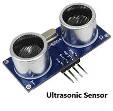
Ultrasonic sensing is one of the best ways to sense proximity and detect levels with high reliability. For this project we used the HC-SR04 ultrasonic distance sensor. This economical sensor provides 2cm to 400cm of non contact measurement functionality with a ranging accuracy that can reach up to 3mm. Each HC-SR04 module includes an ultrasonic transmitter, a receiver and a control circuit. There are only four pins that you need to worry about on the HC-SR04: VCC (Power), Trig (Trigger), Echo (Receive), and GND (Ground). You will find this sensor very easy to set up and use for your next range-finding project! This sensor has additional control circuitry that can prevent inconsistent "bouncy" data depending on the application.
An alternative to this module could be a infrared sensor. But it is more complicated to implement the coding. That is why we went for the ultrasonic sensors.
04. Obstacle Avoidance


Future Goals of the Project
For the future version of this project, we are planning to implement a few new things to make this even better.
-
Attach a independent solar power system to make the robot self sustaining in remote places.
-
Attach several analog sensors like carbon dioxide and nitrogen monoxide sensors with raspberry pi IOT system to check real time environment quality.
-
Better GPS, Compass and Bluetooth components for better navigation and better autonomous driving.
-
Add a surveillance system with camera.
-
Use wifi module to connect to the robot instead of bluetooth for wider range.
Our Project and the UN Sustainable Development Goals
17 Goals to Transform Our World
The Sustainable Development Goals are a call for action by all countries – poor, rich and middle-income – to promote prosperity while protecting the planet. They recognize that ending poverty must go hand-in-hand with strategies that build economic growth and address a range of social needs including education, health, social protection, and job opportunities, while tackling climate change and environmental protection.
Robots are becoming more accurate, sophisticated, and effective, making them potentially useful in a host of development programs. Innovators are realistically imagining a future where robots and self-driving cars can diagnose diseases, prepare meals, and deliver aid. Similarly, artificial intelligence is being used to support the Global Goals.
Our self driving robot is in accordance to the UN SDG goals. The World Food Programme is one of the first responders to areas of war, civil conflict, and natural disasters. For example, in February 2017 alone, WFP brought food assistance to more than 3.5 million people in Syria. However, the envoys delivering food and assistance aid into these conflict settings are often at risk. That is why WFP is exploring how they could use self-driving truck to support the future of humanitarian aid. There are fantastic new ways in which robots can save resources and produce green technologies of the future. In a statement, the UNECE said that automated vehicles have the potential to create safer, more efficient and environmentally friendly transport, which could reshape entire sectors of the economy and improve the lives of millions of people, notably those unable to drive or with limited access to mobility.

Advancing the Sustainable Development Goals (SDGs) using Autonomous Driving

Aside the UN SDGs, autonomous vehicles have the potential to impact society significantly in the coming years. On the positive end, the number of vehicle crashes could be reduced, and travel time can be used more effectively which could result in an annual societal benefit of more than $750 billion in the US alone. When thinking of autonomous vehicles, people often focus on the car and the technology behind it. However, much of the complexity lies in bringing together all of the other supporting parts of the system, from insurance to commercial models. There are also significant challenges in balancing the positive and negative impacts, with improved safety and a reduced environmental impact on one side against loss of employment on the other.
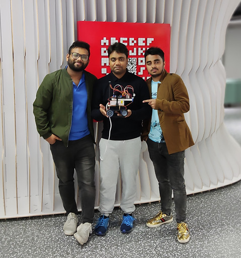
Credits
Self Driving Robot -
Coding by -
MD SEZADUR RAHMAN - 22151470
Software simulation and research -
MD FARHAD HOSSAIN - 22151447
MD Kawsarul Islam - 22151443
Hardware design -
MD SEZADUR RAHMAN - 22151470
MD FARHAD HOSSAIN - 22151447
MD Kawsarul Islam - 22151443
Web design -
MD SEZADUR RAHMAN - 22151470
MD FARHAD HOSSAIN - 22151447
Let’s Work Together
Get in touch so we can start working together.